
Электричество доклад на английском
Обновлено: 31.05.2024
CONTENT
the introduction…………………………………………………….3
Alternative Energy – The Solution To The Fossil Fuel………………………………………………………………………………4
1.1 The history of Alternative Energy……………………………………..4
1.2 Alternative energy is crucial to the preservation of a habital environment………………………………………………………………………6
1.3 Modular Wind Amplified Rotor Platform……………………………….7
1.4 Geothermal energy……………………………………………………..8
conclusion…………………………………………………………….9
BIBLIOGRAPHY…………………………………………………………10
Residual-current device
A residual current device (RCD), similar to a residual current circuit breaker
(RCCB), is an electrical wiring device that disconnects a circuit whenever it
detects that the electric current is not balanced between the energized conductor
and the return neutral conductor. Such an imbalance is sometimes caused by
current leakage through the body of a person who is grounded and accidentally
touching the energized part of the circuit. A lethal shock can result from these
conditions. RCDs are designed to disconnect quickly enough to mitigate the harm
caused by such shocks although they are not intended to provide protection against
overload or short-circuit conditions.
In the United States and Canada, a residual current device is also known as a
ground fault circuit interrupter (GFCI), ground fault interrupter (GFI) or an
appliance leakage current interrupter (ALCI). In Australia they are sometimes
known as "safety switches" or simply "RCD". They can be found in kitchens,
bathrooms, and other places that can be wet.
Purpose and operation
RCDs are designed to prevent electrocution by detecting the leakage current,
which can be far smaller (typically 5-30 milliamperes) than the currents needed to
operate conventional circuit breakers or fuses (several amperes). RCDs are
intended to operate within 25-40 milliseconds, before electric shock can drive the
heart into ventricular fibrillation, the most common cause of death through electric
shock.
In the United States, the National Electrical Code requires GFCI devices
intended to protect people to interrupt the circuit if the leakage current exceeds a
range of 4-6 mA of current (the trip setting is typically 5 mA) within 25
milliseconds. GFCI devices which protect equipment (not people) are allowed to
trip as high as 30 mA of current. In Europe, the commonly used RCDs have trip
currents of 10-300 mA.
RCDs operate by measuring the current balance between two conductors
using a differential current transformer. The device will open its contacts when it
detects a difference in current between the live conductor and the neutral
conductor. The supply and return currents must sum to zero; otherwise, there is a
leakage of current to somewhere else (to earth/ground, or to another circuit, etc.).
RCDs with trip currents as high as 500 mA are sometimes deployed in
environments (such as computing centers) where a lower threshold would carry an
unacceptable risk of accidental trips.
In some countries, two-wire (ungrounded) outlets may be replaced with
three-wire GFCIs to protect against electrocution, and a grounding wire does not
need to be supplied to that GFCI, but the outlet must be tagged as such. The GFCI
manufacturers provide tags for the appropriate installation description.
Any fault to earth (for example caused by a person touching a live
component in the attached appliance) causes some of the current to take a different
return path which means there is an imbalance (difference) in the current in the two
conductors (single phase case), or, more generally, a nonzero sum of currents from
among various conductors (for example, three phase conductors and one neutral
conductor).
This difference causes a current in the sense coil (6) which is picked up by
the sense circuitry (7). The sense circuitry then removes power from the solenoid
(5) and the contacts (4) are forced apart by a spring, cutting off the electricity
supply to the appliance.
The device is designed so that the current is interrupted in a fraction of a
second, greatly reducing the chances of a dangerous electric shock being received.
The test button (8) allows the correct operation of the device to be verified
by passing a small current through the orange test wire (9). This simulates a fault
by creating an imbalance in the sense coil. If the RCD does not trip when this
button is pressed then the device must be replaced.
Use and placement
In most countries, not all circuits in a home are protected by RCDs. If a
single RCD is installed for an entire electrical installation, any fault will cut all
power to the premises. Normal practice in domestic installations in the UK was to
use a single RCD for all RCD protected circuits but to have some circuits that are
not protected at all. Regulation introduced in 2008 dictate that on all new electrical
installations in the UK, all circuits must be protected by an RCD; however, this
does not affect existing installations.
GFI receptacles in the USA have connections to protect downstream
receptacles so that all outlets on a circuit may be protected by one GFI outlet.
Residual current and overcurrent protection may be combined in one device
for installation into the service panel; this device is known as a GFCI breaker in the
US and as an RCBO in Europe. In the US, RCBOs are more expensive than RCD
outlets.
More than one RCD feeding another is unnecessary, provided they have
been wired properly. One exception is the case of a TT earthing system where the
earth loop impedance may be high, meaning that a ground fault might not cause
sufficient current to trip an ordinary circuit breaker or fuse. In this case a special
100 mA (or greater) trip current time-delayed RCD is installed covering the whole
installation and then more sensitive RCDs should be installed downstream of it for
sockets and other circuits which are considered high risk.
Testing
RCDs can be tested with the built-in test button to confirm functionality on a
regular basis. RCDs if wired improperly may not operate correctly and are
generally tested by the installer to verify correct operation. Use of a solenoid
voltmeter from live to earth provides an external path and can test the wiring to the
RCD. Such a test may be performed on installation of the device and at any
"downstream" outlet.
Limitations
A residual current circuit breaker cannot remove all risk of electric shock or
fire. In particular, an RCD alone will not detect overload conditions, phase to
neutral short circuits or phase-to-phase short circuits. Over-current protection (fuse
or circuit breaker) must be provided. Circuit breakers that combine the functions of
an RCD with overcurrent protection respond to both types of fault. These are
known as RCBOs, and are available in 1, 2, 3 and 4 pole configurations. RCBOs
will typically have separate circuits for detecting current imbalance and for
overload current but will have a common interrupting mechanism.
An RCD will help to protect against electric shock where current flows
through a person from a phase to earth. It cannot protect against electric shock
where current flows through a person from phase to neutral or phase to phase, for
example where a finger touches both live and neutral contacts in a light fitting; a
device can not differentiate between current flow through an intended load from
flow through a person.
Whole installations on a single RCD, common in the UK, are prone to
nuisance trips that can cause safety problems with loss of lighting and defrosting of
food. RCDs also cause nuisance trips with appliances where earth leakage is
common and not a cause of injury or mortality, such as water heaters.
A dangerous condition can arise if the neutral wire is broken or switched off
before the RCD while its live wire is not interrupted. In this situation the tripping
circuitry of the RCD that needs power to be supplied will cease to work. The
circuit will look like it is switched off, but if someone touches the live wire
thinking that it is de-energized, the RCD will not trip. For this reason circuit
breakers must be installed in a way that ensures that the neutral wire is turned off
only at the moment when the live wire is also turned off. Separate single-pole
circuit breakers must never be used for live and neutral, only two or four pole
breakers must be used in cases there is a need for switching off the neutral wire.
Устройство защитного отключения
Устройство защитного отключения (УЗО), более точно устройство
защитного отключения, управляемое дифференциальным (остаточным)
током (УЗО-Д) - коммутационный аппарат, который при достижении
(превышении) дифференциальным током заданного значения при
определённых условиях эксплуатации должны вызвать размыкание
контактов. Такой дисбаланс иногда вызван протеканием тока через тело
человека, который заземлен и случайно коснулся части цепи с током. При
этих условиях может произойти смертельный удар током. УЗО
предназначены для быстрого разъединения цепи, чтобы уменьшить вред
вызванный таким ударом тока, хотя они не обеспечивают защиту от
перегрузки или короткого замыкания.
В Соединенных Штатах и Канаде, устройство защитного отключения
также известно как выключатель неисправности заземления цепи (GFCI),
выключатель неисправности заземления (GFI) или выключатель тока утечки
(ALCI). В Австралии их иногда называют "безопасные выключатели" или
просто "УЗО". Они могут быть обнаружены на кухнях, ванных, и других
местах, где может быть влажно.
Назначение и применение
УЗО предназначены для предотвращения удара электрическим током,
обнаруживая замыкание, которое может быть меньше (обычно 5-30 мА), чем
ток необходимый для стандартного выключателя или предохранителя
(несколько А). УЗО срабатывает в течение 25-40 миллисекунд, прежде чем
электрический ток вызовет фибрилляцию сердца – наиболее частую причину
смерти от электрического тока.
В Соединенных Штатах, согласно Национальным Правилам
Эксплуатации Электроустановок требует, чтобы УЗО защищающие людей от
замыканий, отключали цепь, если ток замыкания превышает диапазон 4-6 мА
в течение 25 миллисекунд. Устройства УЗО которые защищают
оборудование (а не людей), применяются с уставкой по току до 30 мА. В
Европе, в большинстве случаев УЗО применяются с уставкой по току 10-300
мА.
УЗО работает измеряя текущий баланс токов между двумя
проводниками, используя разность токов в трансформаторе. Устройство
откроет свои контакты, когда оно обнаруживает разницу в токе между
рабочим проводом и нулевым проводом. Восстановление питание
возобновляется только когда разница будет равна 0, иначе замыкание тока
может произойти где-нибудь еще (на землю или другой провод и т.п.).
УЗО с уставками по току выше 500 мА иногда применяется в условиях
(например вычислительные центры), где более низкий риск случайных
замыканий.
В некоторых странах, двухпроводные розетки могут быть заменены
трехпроводными УЗО, для защиты от удара электрическим током, в этом
случае заземляющий провод не подключается к УЗО, но розетка должна быть
с соответствующей отметкой.
Пример
На фотографии показано внутреннее устройство одного из типов УЗО.
Данное УЗО предназначено для установки в разрыв шнура питания. Его
номинальный ток 13 А, отключающий дифференциальный ток 30 мА. Данное
устройство является: УЗО со вспомогательным источником питания,
Устройство спроектировано таким образом, что отключение
происходит за доли секунды, что значительно снижает тяжесть последствий
от поражения электрическим током.
Кнопка проверки (8) позволяет проверить работоспособность
устройства путем пропускания небольшого тока через оранжевый тестовый
провод (9). Тестовый провод проходит через сердечник трансформатора тока,
поэтому ток в тестовом проводе эквивалентен нарушению баланса
токонесущих проводников, то есть УЗО должно отключиться при нажатии на
кнопку проверки. Если УЗО не отключилось, значит оно неисправно и
должно быть заменено.
Использование и размещение
В большинстве стран не все цепи в домах защищены УЗО. Если для
электрической цепи установлено только одно УЗО, то при любом
повреждении будет отключаться вся нагрузка. Согласно техническим нормам
в Великобритании одним УЗО защищаются все защищаемые цепи, но не все
цепи необходимо защищать. Согласно правилу введенному в 2008 году все
новые электрические системы должны быть защищены УЗО, однако это
правило не касается уже имеющихся систем.
УЗО в США имеют связь между собой, чтобы была возможность
отключения по цепочке, таким образом все цепи могут быть защищены
одним УЗО.
Защита от статочных токов и сверхтоков может быть осуществлена
одним устройством, устанавливаемым на специальной рабочей панели. Эти
устройства известны в Европе и США как УЗО-Д. В США УЗО-Д более
дорогие чем простые УЗО.
Для питания УЗО необходима лишь одна цепь питания, при условии
что оно правильно установлено. Исключением может быть трансформатор
тока, заземляющий систему, так как их сопротивление может быть выше, и
при замыкании значение тока будет недостаточным, чтобы сработал рабочий
выключатель или предохранитель. В этом случае применяются специальные
УЗО с уставкой по току 100мА (или выше), которые защищают всю систему,
а затем более чувствительные УЗО которые должны защищать цепи с
большим риском удара током.
Тестирование
УЗО может быть протестировано нажатием кнопки “тест”, для
проверки его работоспособности. Если УЗО присоединено неверно, то оно
может не сработать и как правило его настройку осуществляет монтажник,
используя вольтметр, соединив рабочую фазу с землей по внешнему контуру.
Ограничения
УЗО не может полностью исключить риск поражения электрическим
током или пожара. УЗО не реагирует на аварийные ситуации, если они не
сопровождаются утечкой из защищаемой цепи. В частности, УЗО не
реагирует на короткие замыкания между фазами и нейтралью. Должна
обеспечиваться защита от тока перегрузки. Выключатель который
объединяет в себе функции УЗО и защиты от тока перегрузки должен
обеспечивать защиту от обоих типов повреждений. Они известны как RCBO
и выполняются в 1, 2, 3 и 4х полярной конфигурации. RCBO обычно
разделяет цепи небаланса и цепи с током перегрузки, но имеет один
размыкающий механизм.
УЗО поможет защитить человека от удара электрическим током, когда
ток течет через человека из фазы на землю. УЗО также не сработает, если
человек оказался под напряжением, но утечки при этом не возникло,
например, при прикосновении пальцем одновременно и к фазному, и к
нулевому проводникам. Предусмотреть электрическую защиту от таких
прикосновений невозможно, так как нельзя отличить протекание тока через
тело человека от нормального протекания тока в нагрузке.
В результате установки только одного УЗО могут возникнуть
проблемы, т.к. при срабатывании защиты будет проходить потеря освещения
или размораживание пищи. УЗО также доставляет неприятности с
устройствами где утечка на землю является обыкновением, а не причиной
повреждения, как например в водяных нагревателях.
Опасная ситуация может возникнуть когда нулевой провод поврежден
или отключен перед УЗО, а рабочая фаза не отключена. В этом случае ток
необходимый для питания УЗО не будет поступать, и оно не будет работать.
Цепь будет выглядеть отключенной, но если кто-нибудь коснется рабочей
фазы, думая, что она отключена, то УЗОР не сработает. По этой причине
выключатель устанавливается таким образом, что нейтральный провод
отключается только тогда, когда рабочая фаза тоже выключена. Разделение
однополярного выключателя никогда не используется для нулевой и рабочей
фазы, только 2 или 4 полярные выключатели используются в случаях, когда
есть необходимость переключения нулевого провода.
Hydroelectricity
Hydroelectricity is electricity generated by hydropower, i.e., the production of power through use of the gravitational force of falling or flowing water. It is the most widely used form of renewable energy. Once a hydroelectric complex is constructed, the project produces no direct waste, and has a considerably lower output level of the greenhouse gas carbon dioxide (CO2) than fossil fuel powered energy plants. Worldwide, hydroelectricity supplied an estimated 715,000 MWe in 2005. This was approximately 19% of the world's electricity (up from 16% in 2003), and accounted for over 63% of electricity from renewable sources.
Содержание
Работа содержит 1 файл
Hydroelectricity.docx
Министерство образования и науки Республики Казахстан
Кафедра иностранных языков
Специальность 6М071800 - Электроэнергетика
Выполнил Тузельбаев А.Е.
№ зачетной книжки 12М4004
Принял пр. Кожаканова М.Т.
Содержание
4 Составление вопросов к тексту. …………………………………………………… …………. 10
5 Определение видо-временной формы предложений………………………………… …………..10
1 Текст на английском языке
Hydroelectricity is electricity generated by hydropower, i.e., the production of power through use of the gravitational force of falling or flowing water. It is the most widely used form of renewable energy. Once a hydroelectric complex is constructed, the project produces no direct waste, and has a considerably lower output level of the greenhouse gas carbon dioxide (CO2) than fossil fuel powered energy plants. Worldwide, hydroelectricity supplied an estimated 715,000 MWe in 2005. This was approximately 19% of the world's electricity (up from 16% in 2003), and accounted for over 63% of electricity from renewable sources.
Most hydroelectric power comes from the potential energy of dammed water driving a water turbine and generator. In this case the energy extracted from the water depends on the volume and on the difference in height between the source and the water's outflow. This height difference is called the head. The amount of potential energy in water is proportional to the head. To obtain very high head, water for a hydraulic turbine may be run through a large pipe called a penstock.
Pumped storage hydroelectricity produces electricity to supply high peak demands by moving water between reservoirs at different elevations. At times of low electrical demand, excess generation capacity is used to pump water into the higher reservoir. When there is higher demand, water is released back into the lower reservoir through a turbine. Pumped storage schemes currently provide the only commercially important means of large-scale grid energy storage and improve the daily load factor of the generation system. Hydroelectric plants with no reservoir capacity are called run-of-the-river plants. A tidal power plant makes use of the daily rise and fall of water due to tides; such sources are highly predictable, and if conditions permit construction of reservoirs, can also be dispatch able to generate power during high demand periods.
Less common types of hydro schemes use water's kinetic energy or undammed sources such as undershot waterwheels.
A simple formula for approximating electric power production at a hydroelectric plant is: P = hrgk, where P is Power in kilowatts, h is height in meters, r is flow rate in cubic meters per second, g is acceleration due to gravity of 9.8 m/s2, and k is a coefficient of efficiency ranging from 0 to 1. Efficiency is often higher with larger and more modern turbines.
Annual electric energy production depends on the available water supply. In some installations the water flow rate can vary by a factor of 10:1 over the course of a year.
Industrial hydroelectric plants
While many hydroelectric projects supply public electricity networks, some are created to serve specific industrial enterprises. Dedicated hydroelectric projects are often built to provide the substantial amounts of electricity needed for aluminium electrolytic plants. In the Scottish Highlands there are examples at Kinlochleven and Lochaber, constructed during the early years of the 20th century. The Grand Coulee Dam, long the world's largest, switched to support Alcoa aluminum in Bellingham. In Suriname, the Brokopondo Reservoir was constructed to provide electricity for the Alcoa aluminium industry. New Zealand's Manapouri Power Station was constructed to supply electricity to the aluminium smelter at Tiwai Point.
Small-scale hydro-electric plants
Although large hydroelectric installations generate most of the world's hydroelectricity, some situations require small hydro plants. These are defined as plants producing up to 10 megawatts, or projects up to 30 megawatts in North America. A small hydro plant may be connected to a distribution grid or may provide power only to an isolated community. Small hydro projects generally do not require the protracted economic, engineering and environmental studies associated with large projects, and often can be completed much more quickly. A small hydro development may be installed along with a project for flood control, irrigation or other purposes, providing extra revenue for project costs. In areas that formerly used waterwheels for milling and other purposes, often the site can be redeveloped for electric power production, possibly eliminating the new environmental impact of any demolition operation. Small hydro can be further divided into mini-hydro, units around 1 MW in size, and micro hydro with units as large as 100 kW down to a couple of kW rating.
Small hydro schemes are particularly popular in China, which has over 50% of world small hydro capacity.
Small hydro units in the range 1 MW to about 30 MW are often available from multiple manufacturers using standardized "water to wire" packages; a single contractor can provide all the major mechanical and electrical equipment (turbine, generator, controls, switchgear), selecting from several standard designs to fit the site conditions. Micro hydro projects use a diverse range of equipment; in the smaller sizes industrial centrifugal pumps can be used as turbines, with comparatively low purchase cost compared to purpose-built turbines.
The major advantage of hydroelectricity is elimination of the cost of fuel. The cost of operating a hydroelectric plant is nearly immune to increases in the cost of fossil fuels such as oil, natural gas or coal, and no imports are needed.
Hydroelectric plants also tend to have longer economic lives than fuel-fired generation, with some plants now in service which were built 50 to 100 years ago. Operating labor cost is also usually low, as plants are automated and have few personnel on site during normal operation.
Where a dam serves multiple purposes, a hydroelectric plant may be added with relatively low construction cost, providing a useful revenue stream to offset the costs of dam operation. It has been calculated that the sale of electricity from the Three Gorges Dam will cover the construction costs after 5 to 8 years of full generation.
Hydroelectric projects can be disruptive to surrounding aquatic ecosystems both upstream and downstream of the plant site. For instance, studies have shown that dams along the Atlantic and Pacific coasts of North America have reduced salmon populations by preventing access to spawning grounds upstream, even though most dams in salmon habitat have fish ladders installed. Salmon spawn are also harmed on their migration to sea when they must pass through turbines. This has led to some areas transporting spawn downstream by barge during parts of the year. In some cases dams have been demolished (for example the Marmot Dam demolished in 2007) because of impact on fish. Turbine and power-plant designs that are easier on aquatic life are an active area of research. Mitigation measures such as fish ladders may be required at new projects or as a condition of re-licensing of existing projects.
Generation of hydroelectric power changes the downstream river environment. Water exiting a turbine usually contains very little suspended sediment, which can lead to scouring of river beds and loss of riverbanks. Since turbine gates are often opened intermittently, rapid or even daily fluctuations in river flow are observed. For example, in the Grand Canyon, the daily cyclic flow variation caused by Glen Canyon Dam was found to be contributing to erosion of sand bars. Dissolved oxygen content of the water may change from pre-construction conditions. Depending on the location, water exiting from turbines is typically much warmer than the pre-dam water, which can change aquatic fauna populations, including endangered species, and prevent natural freezing processes from occurring. Some hydroelectric projects also use canals to divert a river at a shallower gradient to increase the head of the scheme. In some cases, the entire river may be diverted leaving a dry riverbed. Examples include the Tekapo and Pukaki Rivers.
Comparison with other methods of power generation
Hydroelectricity eliminates the flue gas emissions from fossil fuel combustion, including pollutants such as sulfur dioxide, nitric oxide, carbon monoxide, dust, and mercury in the coal. Hydroelectricity also avoids the hazards of coal mining and the indirect health effects of coal emissions. Compared to nuclear power, hydroelectricity generates no nuclear waste, has none of the dangers associated with uranium mining, nor nuclear leaks. Unlike uranium, hydroelectricity is also a renewable energy source.
Compared to wind farms, hydroelectricity power plants have a more predictable load factor. If the project has a storage reservoir, it can be dispatched to generate power when needed. Hydroelectric plants can be easily regulated to follow variations in power demand.
Unlike fossil-fuel combustion turbines, construction of a hydroelectric plant requires a long lead-time for site studies, hydrological studies, and environmental impact assessment. Hydrological data up to 50 years or more is usually required to determine the best sites and operating regimes for a large hydroelectric plant. Unlike plants operated by fuel, such as fossil or nuclear energy, the number of sites that can be economically developed for hydroelectric production is limited; in many areas the most cost effective sites have already been exploited. New hydro sites tend to be far from population centers and require extensive transmission lines. Hydroelectric generation depends on rainfall in the watershed, and may be significantly reduced in years of low rainfall or snowmelt. Long-term energy yield may be affected by climate change. Utilities that primarily use hydroelectric power may spend additional capital to build extra capacity to ensure sufficient power is available in low water years.
In parts of Canada (the provinces of British Columbia, Manitoba, Ontario, Quebec, Newfoundland and Labrador) hydroelectricity is used so extensively that the word "hydro" is often used to refer to any electricity delivered by a power utility. The government-run power utilities in these provinces are called BC Hydro, Manitoba Hydro, Hydro One (formerly "Ontario Hydro"), Hydro-Québec and Newfoundland and Labrador Hydro respectively. Hydro-Québec is the world's largest hydroelectric generating company, with a total installed capacity (2007) of 35,647 MW.
2 Перевод текста
Гидроэлектроэнергия – электричество произведенная гидроэнергетикой, то есть, энергия произведённая в результате падения или течения воды под действием сил гравитации. Это наиболее широко использованная форма возобновляемой энергии. Однажды построенный гидроэлектроэнергетический комплекс не создает никаких отходов, а также обладает более низким уровнем производства парникового газа – оксида углерода, чем при сжигании органического топлива для получения энергии на станциях. Во всем мире, гидроэлектроэнергетика произвела около 715,000 мегаватт электроэнергии в 2005. Это составило приблизительно 19% всемирного электричества (в сравнении с 16% в 2003), и составляет более 63% электроэнергии из возобновляемых источников.
Большая часть гидроэлектроэнергии создается за счет потенциальной энергии запруженной воды, которая приводит в действие гидротурбину и генератор. В этом случае энергия извлеченная из воды зависит от объема и разницы в высоте между источником и водостоком. Это различие высоты называется напором. Сумма потенциальной энергии воды пропорциональна напору. Чтобы получить очень высокий напор, вода для гидравлической турбины может быть пущена через большую трубу названую шлюзом.
Гидроаккумулирующие электростанции производят электроэнергию во время пиков нагрузки, перемещая воду между резервуарами с различными высотами. Во время низкого электропотребления, избыток энергии используется, чтобы закачать воду в более высокий резервуар. Когда появляется максимум потребления, вода снова спускается в более низкий резервуар через турбину. Гидроаккумулирующие схемы в настоящее время снабжают только важные коммерческие крупномасштабные энергосети сохраняя суточную нагрузку генерирующей системы. Гидроэлектрические станции без возможности сохранять воду называются русловыми ГЭС. Приливная электростанция использует ежедневное повышение и падение воды из-за приливов и отливов; такие источники – очень предсказуемые, и если конструкция водохранилищ позволяет по условиям, то они также могут быть использованы, чтобы генерировать мощность в течение максимумов потребления.
Менее распространенные типы гидро схем используют кинетическую энергию воды или незапруженные источники как например, колесо мельницы.
Существует простая формула, чтобы определять количество электроэнергии произведенное на гидростанции: P = hrgk, где P – мощность в киловаттах, h – напор в метрах, r – расход воды в кубических метрах в секунду, g – ускорение свободного падения 9,8 м/с 2 , и k – коэффициент полезного действия, колеблющийся от 0 до 1. Эффективность часто выше, с более крупными и более современными турбинами.
Годовой объем производства электроэнергии зависит от количества поступающей воды. В некоторых системах скорость течения воды может изменяться с коэффициентом 10:1 в течение года.
Хотя большие гидроэлектростанции генерируют большую часть мировой гидроэлектроэнергии, в некоторых ситуациях требуются небольшие гидроэлектростанции. Такие станции действуют в Северной Америке и выдают до 10 или 30 мегаватт. Небольшая гидроэлектростанция может быть подключена к распределительной сети или может снабжать мощностью изолированных потребителей. Небольшие ГЭС обычно не требуют длительных экономических, инженерных и связанных с окружающей средой исследований с большими проектами, и часто могут быть построены более быстро. Небольшая ГЭС может быть использована совместно с проектом по контролю за наводнениями, для орошения или других целей, обеспечивающих дополнительный доход по проектной стоимости. В местах, где раньше использовались водяные колёса для мельниц и других целей, часто могут быть реконструированы для производства электроэнергии, тем самым исключая новое негативное влияние на окружающую среду. Небольшие ГЭС могут быть в дальнейшем разделены на мини ГЭС, мощностью около 1 МВт по величине, и микро ГЭС, мощностью от 100 кВт вплоть до нескольких кВт.
Небольшие ГЭС особенно популярны в Китае, который имеет более 50% от общего количества небольших ГЭС в мире.
Небольшие ГЭС в диапазоне от 1 МВт до 30 МВт часто доступны у многочисленных производителей использующих стандартные комплектации; один подрядчик может обеспечить все основное механическое и электрическое оборудование (турбина, генератор, элементы управления, коммутационная аппаратура) выбирающиеся из нескольких стандартных планировок подходящих для данного места. Микро ГЭС используются для широкого диапазона оборудования; на маленьких производствах, промышленные центробежные насосы могут быть использованы как турбины, со сравнительно низкой стоимостью по сравнению со специально сконструированными турбинами.
Основное преимущество гидроэлектроэнергии является отсутствие затрат на топливо. На стоимость работы ГЭС почти не влияет увеличение стоимости ископаемого топлива, такого как нефть, природный газ или каменный уголь, а также не требуется никакого импортирования.
Гидроэлектростанции также обладают более длительным сроком службы по сравнению с генераторами, сжигающими топливо, некоторые станции, которые сейчас находятся в работе были построены от 50 до 100 лет тому назад. Обслуживающая стоимость также обычно находится на низком уровне, так как станции автоматизированы и имеют небольшое количество рабочего персонала во время нормальной работы.
В местах, где дамба служит для нескольких целей, гидроэлектростанция может быть сооружена со сравнительно низкой стоимостью, при условии, что доход будет возмещать стоимость работы дамбы. Было подсчитано, что продажа электричества с Three Gorges Dam покроет строительные затраты после 5 – 8 лет работы.
The first machine for producing an electric charge was described in 1672 by the German physicist Otto von Guericke. It consisted of a sulfur sphere turned by a crank on which a charge was induced when the hand was held against it.
The French scientist Charles Fransois de Cisternay Du Fay was the first to make clear the two different types of electric charge: positive and negative.
Benjamin Franklin spent much time in electrical research. His famous kite experiment proved that the atmospheric electricity that causes the phenomena of lightning and thunder is identical with the electrostatic charge on a Leyden jar. Franklin developed a theory that electricity is a single “fluid” existing in all matter, and that its effects can be explained by excesses and shortages of this fluid.
The British chemist Joseph Priestley proved the law that the force between electric charges varies inversely with the square of the distance between the charges experimentally in 1766. Priestley also demonstrated that an electric charge distributes itself uniformly over the surface of a hollow metal sphere, and that no charge and no electric field of force exists within such a sphere.
Charles Augustin de Coulomb invented a torsion balance to measure accurately the force exerted by electrical charges. With this apparatus he confirmed Priestley's observations and showed that the force between two charges is also proportional to the product of the individual charges. Faraday, who made many contributions to the study of electricity in the early 19th century, was also responsible for the theory of electric lines of force.
The Italian physicists Luigi Galvani and Alessandro Volta conducted the first important experiments in electrical currents. Galvani produced muscle contraction in the legs of frogs by applying an electric current to them. Volta in 1800 announced the first artificial electrochemical source of potential difference, a form of electric battery.
The Danish scientist Hans Christian Oersted demonstrated the fact that a magnetic field exists around an electric current flow in 1819. In 1831 Faraday proved that a current flowing in a coil of wire could induce electromagnetically a current in a nearby coil. About 1840 James Prescott Joule and the German scientist Hermann Ludwig Ferdinand von Helmholtz demonstrated that electric circuits obey the law of the conservation of energy and that electricity is a form of energy.
An important contribution to the study of electricity in the 19th century was the work of the British mathematical physicist James Clerk Maxwell, who investigated the properties of electromagnetic waves and light and developed the theory that the two are identical. His work paved the way for the German physicist Heinrich Rudolf Hertz, who produced and detected electric waves in the atmosphere in 1886.
The Dutch physicist Hendrik Antoon Lorentz first advanced the electron theory, which is the basis of modern electrical theory in 1892. The widespread use of electricity as a source of power is largely due to the work of such pioneering American engineers and inventors as Thomas Alva Edison, Nikola Tesla, and Charles Proteus Steinmetz.
Вы можете изучить и скачать доклад-презентацию на тему Electricity. Презентация на заданную тему содержит 12 слайдов. Для просмотра воспользуйтесь проигрывателем, если материал оказался полезным для Вас - поделитесь им с друзьями с помощью социальных кнопок и добавьте наш сайт презентаций в закладки!


Electricity. Electricity is something that we use every day, and sometimes don’t realize how much we use it, or depend on it.
Electric current. A current that always flows in one direction is called a direct current (DC). A battery for example, produces a direct current. A current that flows back and forth is called an alternating current (AC).
In our modern world electricity is used for industry and agriculture, communication and transportation, and for everyday use.
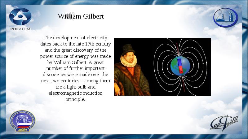
William Gilbert The development of electricity dates back to the late 17th century and the great discovery of the power source of energy was made by William Gilbert. A great number of further important discoveries were made over the next two centuries – among them are a light bulb and electromagnetic induction principle.
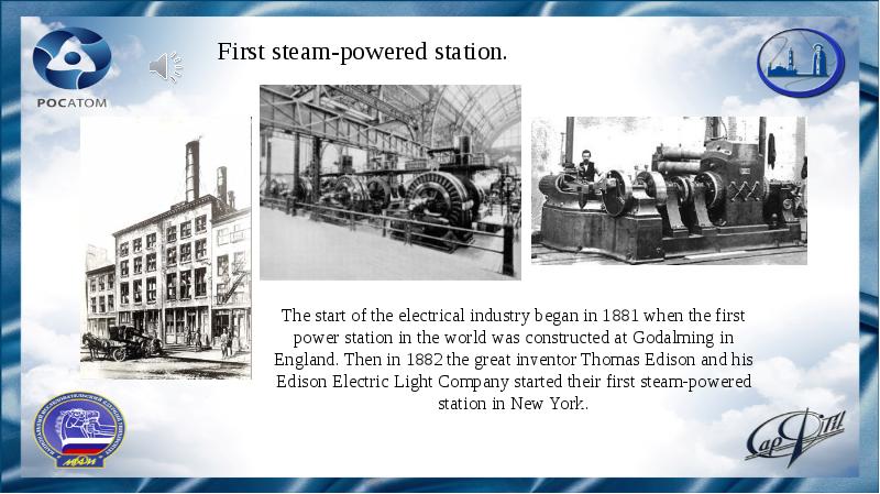
First steam-powered station. The start of the electrical industry began in 1881 when the first power station in the world was constructed at Godalming in England. Then in 1882 the great inventor Thomas Edison and his Edison Electric Light Company started their first steam-powered station in New York.
But what is the electricity? From the scientific point of view, the electricity is a particular set of physical phenomena which is characterized by the presence and the distinctive flow of electric charge.
We use electrical power for heating, cooling and lighting our houses, for cooking food, and for numerous devices and gadgets such TV-sets, computers and smartphones.
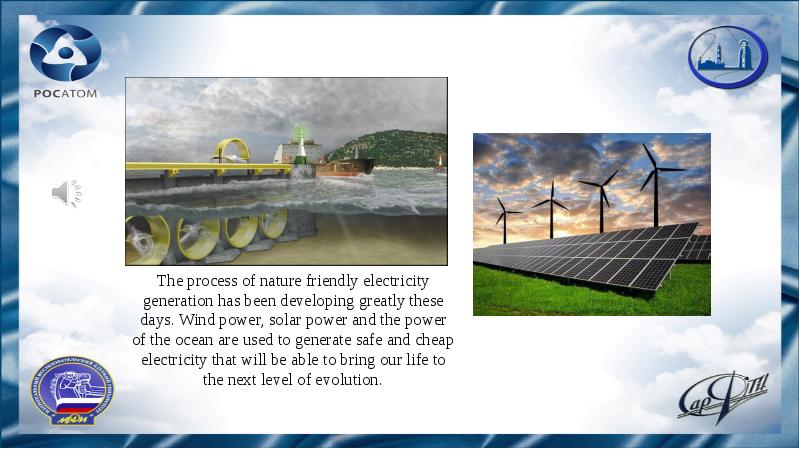
The process of nature friendly electricity generation has been developing greatly these days. Wind power, solar power and the power of the ocean are used to generate safe and cheap electricity that will be able to bring our life to the next level of evolution.
Читайте также: